Introduction to VOC governance methods in steel drum production process
Shanghai Qiaosheng Electromechanical Complete Equipment Co., Ltd. Sun Youlong
Sun Youlong made an exchange speech at the Guilin Steel Bar Industry Conference
First, the source of waste gas
According to the characteristics of the barrel process, in the production process of steel drums, a large amount of volatile organic waste VOC will be produced in the process of painting, leveling and drying. The types of solvents used in the production are complex, and the main pollutants are Toluene, xylene and paint mist particles.
Steel drum production includes inner coating, outer coating and bottom cover inner coating production lines. There are two types of exhaust gas pollution sources:
The first type of pollution source: exhaust emissions from the spray booth and leveling section. A large amount of organic pollutants are generated during the painting process, and the pollution process is more serious as the airflow is volatilized.
The second type of pollution source: exhaust gas from the drying room, because the coating is baked at a high temperature to form a film, the organic solvent is evaporated by heating in a drying room to become a high-temperature gas.
Second, VOC governance methods
1. Combustion catalytic method - high temperature exhaust gas treatment method in drying room
A, features:
1 Applicable to high temperature exhaust gas treatment in drying room, high treatment rate
2 The heat energy after exhaust gas treatment can be reused in the drying room for drying room production (can replace the energy consumption of the oven burner) to achieve energy saving and emission reduction effect.
3 Low investment costs and low operating costs
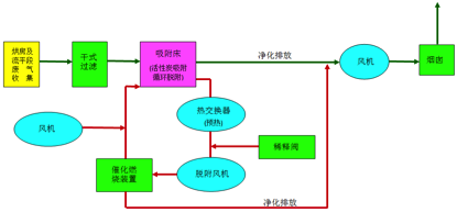
B, process flow
After the exhaust gas is collected, it is sent to the heat exchanger by the exhaust fan to indirectly preheat the exhaust gas (to increase the temperature of the exhaust gas by 30~50 °C) into the environmental protection furnace → burning and heating (one-time purification, temperature condition ≥350 °C)→catalytic reaction ( Secondary purification, temperature condition ≥350 °C) → After the purification, the heat is sent to the drying room for production use (replace the burner on the original drying room) → excess heat is then preheated by the heat exchanger, and then discharged after cooling.
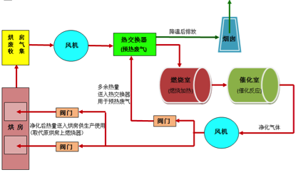
Combustion catalytic process flow chart
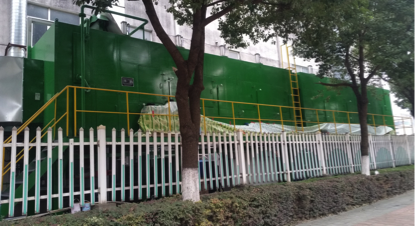
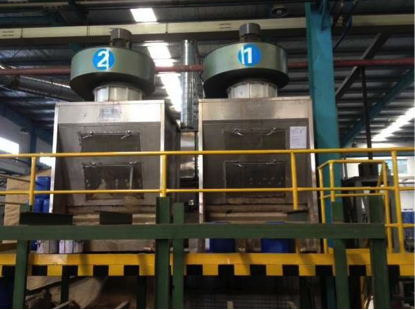
C, reference picture
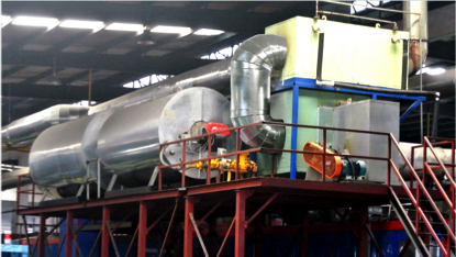
Combustion catalytic method
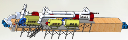
Combustion catalytic structure diagram
2. Concentrated catalytic combustion method - spraying room and leveling section normal temperature exhaust gas treatment method
A, features:
1 Only applicable to the treatment of normal temperature exhaust gas in spray booths and leveling sections
2 The treatment process is complicated (the exhaust gas volume is large, the concentration is low, and it contains certain particle pollution)
3 Extended use cycle of activated carbon by adsorption + cyclic desorption method
4 The leveling exhaust gas is treated at the same time to improve the working environment on site.
B, process flow
Concentrated catalytic combustion process flow chart
C, reference picture
Leveling waste gas treatment physical map
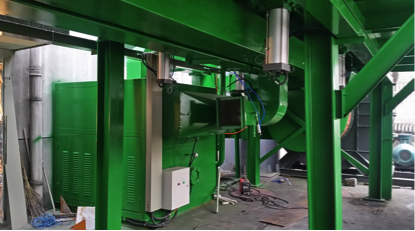
Paint booth exhaust gas treatment physical map
3. Concentrated internal circulation + RTO regenerative thermal oxidation method - VOC centralized treatment method for drum production line
A, features:
1 The whole line of exhaust gas is treated centrally to reduce the exhaust port; the purification rate is high and the purification effect is good; it meets the latest environmental emission standards.
2 The paint room exhaust gas adopts a concentrated internal circulation system, which effectively increases the exhaust gas concentration, reduces the exhaust gas flow, and reduces the investment cost and operating cost.
3 is the current VOC best governance method, industry development trend; higher investment costs and operating costs
B, process flow
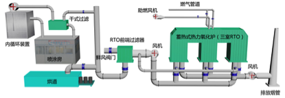
1 Collect the exhaust gas from the spray booth and the leveling section, pass the paint removal device and the dry filter (exhaust gas after dehumidification of paint removal) → through the internal circulation system, partially discharge into the RTO device, and another part into the closed spray booth.
2 RTO device high temperature oxidation process: the paint, leveling and drying room exhaust all enter the regenerator preheating (up to 750 °C) → then enter the thermal oxidation chamber to fully oxidize and decompose (the temperature reaches 760 °C, the organic components in the exhaust gas Complete oxidative decomposition→ The oxidatively decomposed gas enters another set of regenerators and exchanges heat with the regenerative ceramic filler. The heat is stored in the regenerator for preheating the newly entered exhaust gas. The temperature of the gas is lowered → after cooling The gas is discharged through the chimney.
The multiple regenerators of the RTO are automatically switched in turn.
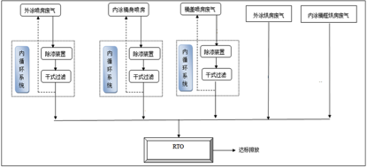
RTO process flow chart
C, reference picture
RTO structure schematic
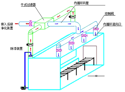
Flowing chamber exhaust gas collection schematic
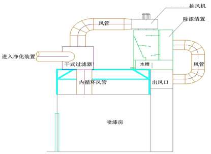
Spray booth waste collection schematic
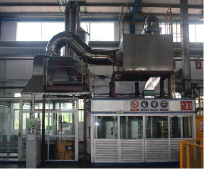
Painting room and leveling chamber exhaust collection physical map
Drying room high temperature exhaust gas collection physical map
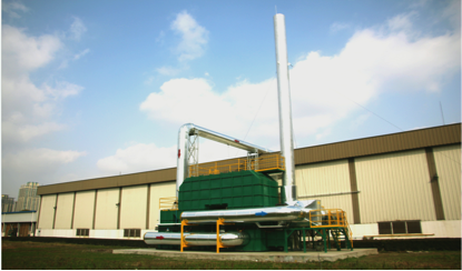
RTO physical outline drawing
Ningbo XISXI E-commerce Co., Ltd , https://www.petspetscleaning.com